
Senior Project Progress Log
Week 27 (July 14 - July 20, 2021)
Now that the system can fully deploy and compact on its own, a push button , shown in figure 70, was added to deploy the tent on its initial launch.
After conducting some tests with the AC system, we ran into an issue with the MOSFETS in which one caught on fire after prolonged use. The team quickly remedied the solution by adding an H-bridge , shown in figure 71, that had a heat sync which runs at higher amperage and can dissipate the heat that could occur after prolonged use of the system. This also allows for the fans to run with a pulse width modulated signal so that it runs at a lower speed. The team also added a safety feature by adding a on off switch for the battery using a key, shown in figure 72. This effectively makes an emergency stop switch that cuts power to the system in the event of an unforeseen malfunction.
A video recording of the AC function is shown in Video 13
The team is continuing to run tests and drafting the report
Video 13
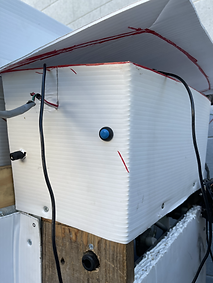
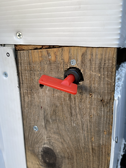

Figure 70
Figure 71
Figure 72
Week 26 (July 7 - July 13, 2021)
The tent can now deploy and compact on its own without assistance(Video 11-12).
Now the team is continuing to run tests and drafting the report.
Video 11
Video 12

Week 26 (June 29 - July 6, 2021)
Emmanuel was able to solve the issue with the user interface. He found out that all the functions that called for the other files to run the individual modules needed to be called by a timer to update regularly as the system is running. Now the UI can control all the modules in the system simultaneously. A demonstration of how it functions is shown in Video 10
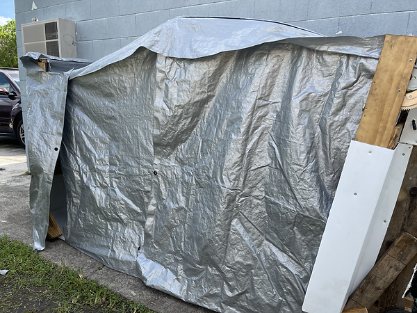
With this the team was able to set up the control for the AC system by connecting MOFSETS to the sources of the AC and have it controlled by the raspberry pi. They also enclosed the system by adding tarp and corrugated plastic around the frame. They also added a boost converter to the solar panels to boost the signal received from them.
They began testing the entire product by launching the system but they ran into an issue with the deployment system. They solved that it had something to do with the H-Bridge malfunctioning after multiple tests and so they had to acquire a new one. But while they were doing that they tested the AC system and the rest of the modules while manually deploying the tent.
Video 10


Figure 65
Figure 66
Figure 67
Figure 68
Figure 69
Week 26 (June 22 - June 28, 2021)
The team continued to work on the control module. Emmanuel was able to trouble shoot the display so that it would show the temperature readings from the temperature sensors and update regularly as the temperature would change. He was also able to relay the information to the AC control program so that it could interface with the AC system.
The team was also able to solve the problem with the deployment of the modules. We figured out that the code we were using for the H-bridge was not correct and it was sending a high signal on both input pins. We changed the code and applied it to the H-bridge with small motors and it worked as we desired. We then applied it to the deployment system and tweaked the duty cycle and the time it is running so that its deployment is controlled.
Video 9
Week 25 (June 15 - June 21, 2021)
Joseph worked on troubleshooting the issues we were facing with the control module. After some testing we found out that the H-bridge we acquired was not functioning as we desired so Joseph went ahead and created one from scratch. After some manual testing he got his design to work. But after running the motors code that we originally created, it did not function as desired. So the team is working on tweaking the code to work with the new system.
While Joseph was troubleshooting the control Module, Emmanuel started drafting the report.
Week 24 (June 8 - June 14, 2021)
The team worked on testing the programs we created to run the system. Joseph realized that the issue we were having with the temperature sensor not being detected by the raspberry pi was due to the pins necessary to read the sensors were being occupied by the display that we had. So the team is deciding to buy another display that will run through the HDMI port that is available on the pi. With that we applied the appropriate pins and tested the code (Figure 64) and we successfully were able to make the temperature sensors function (Video 7).
With that, Emmanuel worked on cleaning up the code for the rest of the system. The goal is to have a file run once the raspberry pi is booted up. Which will run the UI (Figure 65) as well as control the system from that UI. Though not complete Emmanuel demonstrates its possible functionality (Video 8).
Emmanuel reconfigured the previous code to run the motors to better suit the requirements of the system. Though the team ran into an issue with trying to test the code to run the motors. From the troubleshooting that we did we discovered that it might not be the code that is not functioning but the H-Bridge was not receiving the signal from the raspberry pi to activate the motors. The team is deciding on buying another H-Bridge to see if that will solve the problem.


Figure 64
Figure 65
Figure 66
Video 7
Video 8
Week 23 (June 1 - June 7, 2021)
The team continued to add to the previous progress of the project by attaching wheels to the outer extremity of the tent (Figure 59). They were also able to successfully test the deployment of the tent with a controlled expansion, having Joseph control the motors, simulating how it would deploy on its own (Video 6). The test deployment made us realize that we need to specifically control the motor speed. To add more stability we added anchors to the main body of the AC system (Figure 61) so that it stays stable as the tent is deploying. With that we also added tires to the main body so that it would be mobile and easier to move around, as well as magnets to lock the panels to the main body of the AC system.
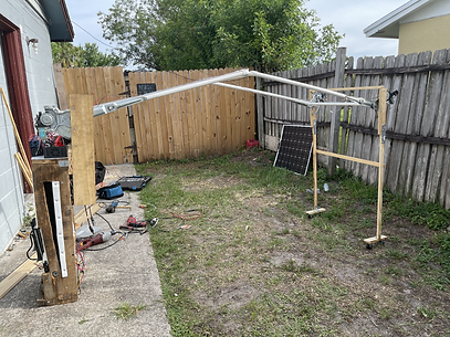
Figure 60
Video 6


Figure 61
Figure 62
Figure 63
Week 22 (May 25 - May 31, 2021)
Joseph found a solution to our weight distribution problem. He found gear motors that are meant for car windows, which have a lot of torque and locks in place at the angle that we need it (Figure 55). The team then went ahead and reconfigured the motors to fit our design (Figure 56), and during the first round of testing it held the weight of one frame and solar panel with ease. The team then continued to modify the rest of the design so that we can apply a second set of motors on the outer extremity (Figure 58). These new motors allowed us to remove the weight of the motors from the center hinge that connected the two panels together, reducing the load on the roof of the tent. to connect the two panels together, we placed door hinges between them so that they could freely move (Figure 59).


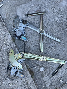
Figure 55
Figure 56
Figure 57

Figure 58

Figure 59


Week 21 (May 18 - May 24, 2021)
The team attempted to solve the weight issue of the frame by adding gas lift spring rods to the back panel of the frame. This proved to hold the weight of a single panel (Shown in Figure 50) though with some draw backs. The strength of the lifts were so strong that it created a bowing on the frame (Shown in Figure 49), which caused a lot of tension on to the back motors and resulted in one of them failing in a test.
Though after realizing that the lifts can hold up one panel, we decided to add the second panel with the outer extremity to see if it can hold its own weight. After one test we realized that the outer extremity we designed was not stable enough to move out in the way we expected. Which caused the middle hinges to be unstable as well. Coupled with the weight of the middle motors and the weight of the panels itself. The lifts we added still did not provide enough support to the middle motors, and so two of the three middle motors failed during testing. Now the team is trying to solve the issue of having the frame hold up itself after deployment.
Apart from the updates on the tent deployment system, Emmanuel went ahead and continued to work on the control module. He was successfully able to apply the UI on to the display on the raspberry pi (Shown in Figure 53) as well as created a way to access the pi remotely so that the team didn't have to depend on the display to operate the pi. He also extended the display away from the raspberry pi so that it would create some room to access the other available GPIO pins. This was so he could wire together all the devices like the H-Bridge and temperature sensor to the pi so that when the tent system is complete it will be as simple as directly connecting the peripherals to the pi itself. Now he is working on finding out a way to launch the UI as soon as the pi gets activated.
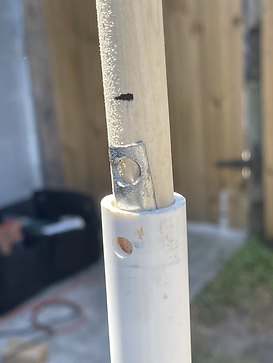

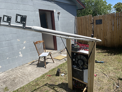
Figure 48
Figure 49
Figure 50
Figure 51
Figure 52

Figure 53

Figure 54
Video 5
Week 20 (May 11 - May 17, 2021)
After a test with the 3 motors from the middle hinge, two motors failed after pushing it to a point at which it could not move further. After breaking apart the motor we realized that this caused the gears inside the motor to break, resulting in the motors not locking anymore. This made us realize that we cannot rely on the natural locking mechanism of the motors to hold the system in place, because any major force that directly impacts the system while the motors are locked could cause them to fail and could pose a danger to the occupants of the tent. To solve this the team is planning on designing a locking mechanism that has the frame and panels support itself instead of the motors supporting the weight of the system on its own.
On the same test we realized that the motors did not lock tightly enough to the gear head that we attach to the armature. So we decided to drill holes through the armature so that the screw could lock in place better. Giving the motors a better hold on to the rest of the system.
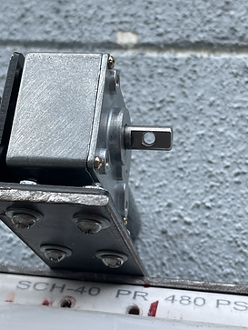


Figure 46
Figure 47
Figure 45
Week 18-19 (May 4 - May 10 , 2021)
After the tests we conducted in the last progress log, we decided to add a third motor to the center hinge of the panels. This provided more strength to the hinge design as well as more stability to avoid having the motors fail by carrying too much weight. This functioned well as the 3 hinge design was able to lift the weight of both panels and the frame.
From there the team was confident enough to move forward and so we created the outer extremity of the tent deployment system and added one motor as the hinge to control the movement of the extremity as the tent is deploying.


Figure 43
Figure 44
Video 4
Week 17 (April 27 - May 3, 2021)
Since the team finally found motors that is able to support the weight of the frame and a solar panel. The team continued to attach the second frame and solar panel to see if it can support the weight of them both. We then conducted test to see if it can hold the weight of both panels. After 4 successful attempts the motors failed. We were concerned that this could happen in future tests so we are deciding to add a third motor to add more strength to the hinge as well as more stability.

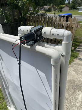


Figure 39
Figure 40
Figure 41
Figure 42
Week 16 (April 20 - April 26, 2021)
The team acquired new motors with a 45kg capacity rating. Since we got new motors we had to remodel the hinge that we made from the previous update. Through testing we were able to lift the frame and solar panel simultaneously. The team can now progress to building the rest of the frame. Through testing we recognized that there is a lot of weight being lifted by the motors, even at their high torque rating we want to avoid the possibility of it failing after multiple tests so the team is deciding to add more motors of the same caliber to the opposite ends of the frame to add more lifting force for the deployment system, reducing the load on each individual motor.


Figure 36
Figure 37
Figure 38
Video 3
Week 13-15 (March 30 - April 19, 2021)
Due to the amount of work required for the project the team decided to withdraw for the semester to give us more time to work on the project. The team keeps running into the issue of not having strong enough motors to perform the necessary task of deploying the tent system and it is holding us back from progressing any further.
The team acquired motors that could be promising but the old design of the frame the we built could not accommodate for the shape of the motors. So, Emmanuel suggested to remodel the frame with PVC pipes so that we could make the design modular. Making it easier to replace the motors without having to replace the entire frame.

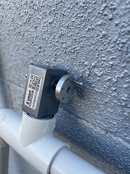


Figure 34
Figure 35
Figure 33
Figure 30
Figure 31
Figure 32
Week 12 (March 23 - March 29, 2021)
Emmanuel has set up the wiring that connects the raspberry pi to the H-bridge. This is so the pi can control the direction of the motor as well as connect it to a supply more appropriate for the motor at 24v. It functions by sending an output from one GPIO pin from the pi to the H-bridge, allowing current to flow in one direction. It can then send a second output from another GPIO pin to allow current to flow in the opposite direction. This will be used in the tent deployment/contracting phase of the system. Where the motors will run one direction in deployment, and the opposite direction for contraction.
Emmanuel has also set up the temperature sensor that will be used to monitor the outside and inside temperatures. The code in the bottom shows how this will be displayed on the monitor.
Emmanuel has also drawn up a schematic of how the system will look, shown bellow are the rear side view of the system in its deployed and contracted state.
Research into DC circuitry isolation for better motor performance without affecting the operation of other components were conducted.


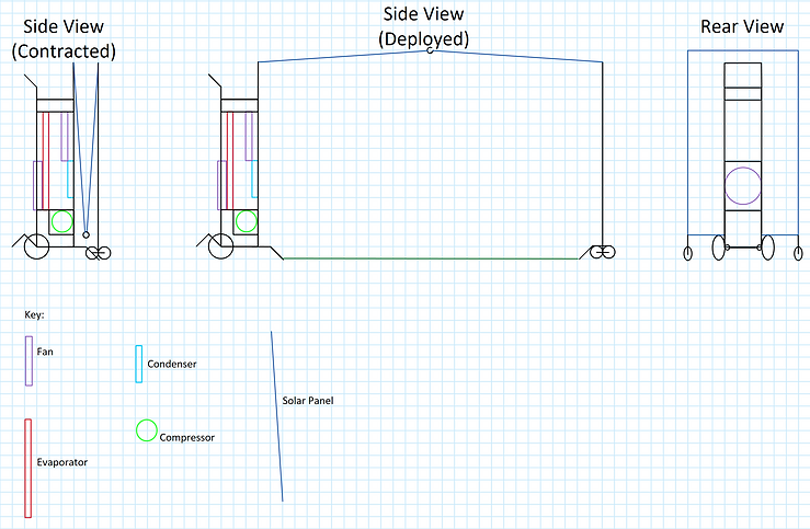
Figure 28
Figure 29
Figure 29
Week 11 (March 16 - March 22, 2021)
Emmanuel started programing the raspberry pi. He was able to make the display function on the raspberry pi, as well as create the code for the graphical user interface (GUI). He also worked on creating the code for the motors to turn clockwise and counter clockwise. He intends to test it out on the motors first and then create a code that will require user input to run the motors when deploying and contracting the tent. He has also figured out how to use the temperature sensors that we acquired for the project and intends to display the information through the GUI, so that the user can see the inside and outside temperature of the system.
A motorized hinge system placed in the center of the tent deployment system instead of the extremities is being adopted to reduce the weight seen by the motors, hence reducing the necessary torque needed.


Figure 27
Figure 25
Figure 26
Week 10 (March 9 - March 15, 2021)
The team figure out the stability issue of the frame by welding two steel pieces together to form a tighter seal. Making the entire frame of the panel into one piece.
The team also designed a hinge system that would connect both panels together using a door hinge to attach to the frame and pinching it into the motor head. While the motors were held together by a light weight PVC pipe that would hold them in place when the motor turned on.
We then attached motors to the furthest extremity of the frame and tested out if the motors would give enough torque to move the system. Unfortunately the motors were not strong enough to push the frame without the solar panels attached to them. This left us looking for other motors that we could use as an alternative to the ones we already had.
***The AC system was tested for frequencies that allow an output of 5-10 degrees cooler than ambient temperature. Test shows that a frequency of 95Hz on the VFD allowed for such output to be observed.


Figure 22
Figure 23
Figure 24
Figure 21
Figure 19
Figure 20
Week 9 (March 2 - March 8, 2021)
The drier and filter was replaced.
System is vacuumed
system vent was sealed
Wire selection done: Wire sizing for both 3-phase and single phase are similar, the major difference was observe in wire material. If copper is the material of choice, wire size would need to be 14AWG whereas for aluminum we would need 12AWG wires.
http://wiresizecalculator.net/
For the DC wire size, 6AWG was chosen as it allows for a current flow of up to 70A. See the chart bellow:
http://assets.bluesea.com/files/resources/newsletter/images/DC_wire_selection_chartlg.jpg


Figure 17
Figure 18
Week 8 (Feb 23 - March 1, 2021)
To fix the issue of welding the frame together, the team decided to screw in corner pieces to hold the frame together. The team got together to put the frame on the solar panels, but ran into the issue finding out how to attach the motors that we previously purchased as the hinge between the panels and the AC system. The team is now currently looking for another motor to use that we can attach to the frame
Test were conducted to get an idea of how frequency affect the power usage and cooling of the system. A power consumption of approximately 2.7 Watts was observed from the VDF. An approximate power consumption of 300W was observed while operating the VFD at 94Hz. Upon startup of the system, the compressor was observed to consume about 500W for that same 94Hz. This test was done using the 48V lithium iron battery. The results can be seen in the following video and was mainly focus on compressor power consumption:
Another test was done with the fan connected t the same power source but the initial power draw of the fan caused the power inverter to go into a short circuit mode. For that reason, circuitry that feeds into the Power inverter was modified to include a capacitor to make up for the power draw. a capacitor will also be included into the branch source for the Raspberry pi buck converter. The video bellow shows the testing with the fan causing the short circuitry. and the picture show capacitor being included in new design:
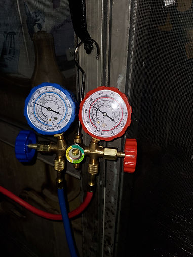
Further testing using regular grid power of 240V shows that at approximately 172Hz, the system was consuming approximately 1124Watts and outputting an increasing pressure of 150psi on the height pressure line while maintaining 35psi on the low side. Keep in mind that the maximum safe operation pressure of the system is about 250 on the high side at which point the safety switch will cut the compressor off. Also high operating muggings is between 198-230psi.


Figure 16
Figure 14
Figure 15
Figure 13
Video 1
Video 2
Figure 11
Figure 12
Week 7 (Feb 16 - Feb 22, 2021)
Joseph solved the leaks by adding hoses and clamps to the modified joints. The 4th compressor that he acquired from the junkyard endures through the preliminary tests and now the system works as desired. The system runs at less 720 Watts, further and and more specific power usage will be obtained with further testing.
He is now currently testing the system with the acquired parts of the power module.
Emmanuel has tried to weld the frame of the tent together. Unfortunately the methods at which he tried to weld them together were unsuccessful. He first tried aluminum welding, which didn't work because the material wouldn't get hot enough to weld the materials together. He got together with Joseph who has prior experience with stick welding, but that didn't work because the process was meant for steel work and so the material got too hot and melted. The team is now trying to figure out a way to put this together.


Figure 7
Figure 8
Figure 9
Figure 10
Week 6 (Feb 9 - Feb 15, 2021)
The team made a change to the size of the tent. Due to the size of the solar panels we acquired it was not feasible to create a tent big enough to fit 4 people and also be compact. Se we decided to change the size of the tent to only accommodate for one person.
Joseph had to acquire a new compressor for the AC system, we had to exchange the compressors 3 times because the ones he previously got were either defective or gave out at some point during preliminary tests. The third compressor worked properly but he realized that the brass compression fitting didn't work, and leaks were discovered in the system.
Emmanuel has acquired the parts for the tent deployment. He has also sketched the schematic for the tent, which is shown below. He is building the frame from scratch, currently he is acquiring the tools needed to put them together.

Figure 6
Week 5 (Feb 2 - Feb 8, 2021)
Emmanuel has purchased the corrugated plastic that will serve as the base for the solar panels. He has also purchased an extension pole and modified it to work congruently with a motor. Parts for the hinge that keeps the solar panels together is being ordered. He is currently researching a hinge that will work best with the extension pole. He is also looking for a frame that can mount all of this together as well as keeping the panels rigid.
Joseph obtained/exchanged the compressor for the system, but the compressor was defective. He is considering in exchanging it for another compressor from the same junkyard. The system is taken apart and retrofitted it with rubber O rings to assist in the leaks at the compression fitting joints. Tests were ran, and the leaks were reduced but not completely.
Week 4 (Jan 26 - Feb 1,2021)
The buck converter design simulation has been fixed and ran without errors. Keep in mind that output resistor might change to account for the current flow adjustment in the actual design since that couldn't be accounted for in the simulation. Input resistors for the 555 chip might also change due to current output rating of the battery of choice. Calculations and Simulation can be seen bellow: (Notice how capacitance and inductance values had to change due to output frequency of the 555 chip changing when connected to the buck converter);
***Note: different mosfet and
diodes are being considered to
accomodate the high output.


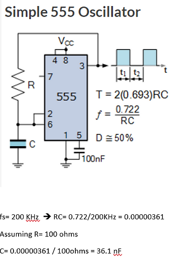

Figure 5


Week 3 (Jan 19 - Jan 25,2021)
The components of the AC system are assembled into the frame. Modifications were made to the original AC hose system from Toyota to fit the custom design. An air compression test was then conducted to test for leaks around the compression fittings used to modify the AC hose system. This test revealed leaks that prevented a startup of the unit as a whole for further test on operation and power consumption on the compressor. The assembled hose system can be seen below:
Research on buck converter for the power module were conducted. A 720W buck converter was found for a decent price given budget consideration. This converter is to power deployment and the AC system. Powering the microcontroller will be handled by a different buck converter and isolated in part from the main buck power source.
Research into buck converter design using a 555 oscillator chip were conducted for higher power output. Buying the parts and building our own buck converter would be cheaper and reduce the spent dollar amount in our budget. Design simulations were attempted and circuit is shown bellow:
Upon analysis, the 555 chip failed to generate the square-wave necessary for the proper operation of the system as a buck converter.
Power consumption of components that are planned in the design were researched for a power budget sheet. It was found out that the 12V fan motors for the are meant for a max operating current of 6A, thus a max operating power of 72W for the fans. A 400W operating power is budgeted for the AC compressor. The microcontroller operates at 15W. The 24V motors that will constitute the hinges of the deployment system have a rated-load current of 0.20A, thus 4.8W per motor.
Emmanuel conducted research on the method of deploying the tent. The team has agreed on using telescoping arms to deploy and compact the tent. Currently we are researching the material we will be using for this. We are considering on either using a product called INFINITubeV telescoping round tubing or PVC pipes to save money on the budget.
Figure 4
Figure 1
Figure 2
Figure 3
Week 2 (Jan 12 - Jan 18,2021)
Joseph is assembling the AC system. This entails building the system's frame to facilitate putting all its components together. Due to complications with his computer there will be a delay on testing the AC system. Also waiting for delivery of hybrid compressor oil to run AC test.
AC unit will also be tested for leaks due to modifications that needed to be carried out on the original hose system.
Due to the large load of work that is required for this project we decided on modifying a tent that we already own instead of making it from scratch. Emmanuel is researching the skeletal system that will be used for deployment process of the tent. He is considering creating a pulley system that would be run through motors connected to the main system, similar to how bi-folding gates work. He is currently researching a material that is light enough to be lifted by the motors as well as hold the tent together.
Week 1 (Jan 5 - Jan 11,2021)
The team has acquired the parts for the AC system as well as some parts of the power module. There has been some testing on the solar panels and assembling of the AC unit has begun.
Assembling AC unit. encountered complications that requires modification to the original hose assembly.